


Please Leave Us A Message
Privacy statement: Your privacy is very important to Us. Our company promises not to disclose your personal information to any external company with out your explicit permission.

 August 16, 2023
There are many methods of sun tracking, which can be divided into two methods, namely photoelectric tracking and tracking according to the movement of the sun. The advantages of the photoelectric tracking device are high sensitivity, simple structure design, and can eliminate accumulated errors through feedback, which has a great advantage. The key component is a photoelectric sensor, and a photoresistor is commonly used. Due to the discontinuous placement of the photoresistor and the influence of ambient scattered light, the system cannot track the sun continuously and has limited accuracy.
Therefore, the structure of the photoresistor needs to be optimized, and the method of increasing the number of photoresistors will cause a complicated structure of the device and increase the cost. Through analysis, the use of an image sensor instead of a photoresistor to detect changes in the solar position can accurately and quickly obtain solar position information, thereby improving tracking accuracy. At the same time, the structure is simplified and the cost is reduced.
1 Overall system design
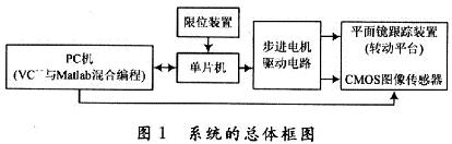
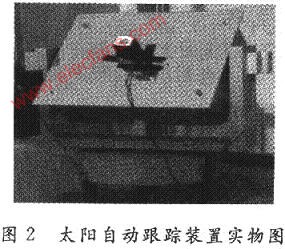
The system is mainly composed of plane mirror tracking device, control and driving circuit, azimuth limit circuit, CMOS image sensor (with Bard film filter) and other parts. The overall design block diagram of the system is shown in Figure 1. The physical diagram of the tracking device is shown in Figure 2, and the image sensor is fixed at the center of the plane mirror. Image sensor products are mainly divided into CCD, CMOS and CIS sensors. At present, the CMOS type is not only inexpensive, but also has digital output and software programmable control, which greatly reduces the difficulty of system design and improves the flexibility, anti-interference and stability of system design.
The CMOS image sensor meets the system design requirements. The tracking controller uses Logitech's QuickCam series network camera, which has the characteristics of low power consumption, low cost, single power supply drive, and easy implementation of system-on-chip integration. The windowing feature can set the size of the effective image data window according to actual needs, thereby avoiding the collection of invalid data and reducing the storage space.
Because the sunlight is very strong, it is necessary to add a Bard film filter to the camera when collecting images. Experiments show that after adding two layers of filters, the resulting image is better.
The working process of the system is: when starting, the host computer VC ++ calls the sun function in the apparent sun movement law to obtain the altitude angle and azimuth angle of the sun, and converts it into the number of steps of the pitch and horizontal stepper motor, and the single-chip microcomputer Communicate and drive the tracking device to ensure that the solar spot fits into the viewing angle of the CMOS image sensor.
Realize the joint programming of VC ++ and Matlab through MCC, and control the image sensor to collect the solar spot image in real time. The VC ++ program is set to automatically call the sensor every 5 minutes to take a picture. The returned image is processed by Matlab to calculate the deviation of the solar spot centroid coordinate and the image center coordinate, which is converted into the number of steps that the horizontal and pitch motors need to adjust, and returns to VC ++, once again sent to the single-chip microcomputer, drive the stepper motor action, and then finely adjust the plane mirror tracking device, so that the sun spot is always in the center of the image.
When the thick cloud layer blocks the sun, or the sun spot cannot appear in the sensor's view due to other reasons, VC ++ calls the clock tracking algorithm and continues to track until the cloud layer has passed before using the image sensor tracking again.
2 The design of the image sensor tracking the sun in real time
2.1 The first positioning of the tracking controller
At startup, the VC ++ program in the host computer first calls the sun function in the apparent sun movement law (there is no need to call it again during the tracking process), returns the solar altitude angle and azimuth angle at this time, and converts it to the pitch and azimuth stepper motor The number of steps and data are sent to the single-chip microcomputer to drive the tracking device to ensure that the sun light spot fits into the angle of view of the image sensor. The subroutine gets the number of steps it needs to run and lists some codes:
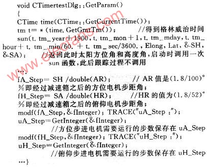
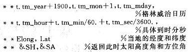
The meaning of each variable in the sun () function:
The communication protocol between PC and SCM is as follows:
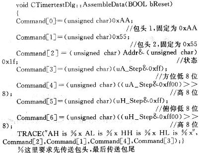
The status is defined as follows:

Among them: When 6,5 must be 1 at the same time, the system is reset.
2.2 Automatic tracking principle of image sensor
VC ++ is set to automatically call the sensor every 5 minutes to take a picture. The returned image is processed by Matlab to calculate the deviation of the center of mass coordinates of the sun from the center coordinate of the image, and converted into the number of steps that the horizontal and pitch motors need to adjust, and send it again The single-chip microcomputer drives the stepping motor, and then finely adjusts the plane mirror tracking device to realize continuous automatic tracking of the sun.
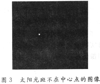
FYP is defined as the number of steps the pitch stepper motor should run, and FWP indicates the number of steps the azimuth stepper motor should run. The azimuth stepper motor is actually (1.8 / 100) ° for each step, and the pitch stepper motor is (1.8 / 52) ° for each step. When the system is actually running, the light spot is set to the coordinates of (160, 120) at the center of the image, and the image FYP is moved down to 50; the image FWP is moved to the right to 160. If the solar spot is not at the center point, as shown in Fig. 3, the Matlab program execution result is the spot image coordinates (115, 117), the number of spots is 1, the corresponding FYP is 1, and the FWP is -46.
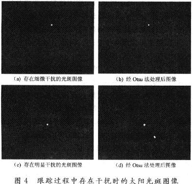
The image processing process uses the maximum between-class variance method Otsu, which is derived based on the principle of least squares. It selects the threshold based on the histogram. The basic idea is to divide the histogram into two groups at a certain threshold. The threshold value is obtained when the variance of the two groups divided is the largest. Variance is a measure of the uniformity of the gray distribution. The larger the variance value, the greater the difference between the two parts that make up the image. When part of the target is wrongly divided into the background, or part of the background is divided into the target, the difference between the two parts becomes smaller, so The segmentation that maximizes the variance between classes means that the probability of misdivision is the smallest. Otsu algorithm has the advantages of simplicity, fast segmentation speed, etc. It is very sensitive to noise and target size. It has a good segmentation effect for images with high signal-to-noise, and is considered to be one of the best methods for automatic threshold selection.
Figure 4 is the image when the solar spot is disturbed. Comparing Figure 4 (a) and Figure 4 (b), we can find that the Otsu method can effectively eliminate the subtle interference in the image. Fig. 4 (c) is processed by the Otsu method to obtain Fig. 4 (d). The spot image coordinates (160, 120), the number of spot is 2, corresponding to 0 for FYP and FWP. From this, it is judged that there is obvious interference in the captured image, and the program sets FYP and FWP to 0 to ensure the reliability of the system.
In general, the image sensor is used for tracking, but when the sky is cloudy or thick clouds appear, the sun spot cannot appear in the sensor perspective. VC ++ immediately calls the clock algorithm to calculate the tracking controller according to the angle of the sun's movement in the sky every minute.5 The angle that min should rotate to determine the speed of the stepper motor, so that the device changes accordingly according to the position of the sun.
2.3 System software design
The main part of the software is the PC part, and the PC environment is Windows XP, using software Microsoft Visual C ++ 6.0 and Matlab 7.0. At startup, VC ++ is responsible for calling the sun function once, returning the current altitude and azimuth of the sun, and converting it into FYP and FWP running steps. By calling the Windows API function, the data transfer between the host computer and the single-chip computer is realized. The joint programming of VC ++ and Matlab is realized through MCC, and the camera is controlled to collect the solar spot image, which is converted into FYP and FWP correction steps according to the deviation of the solar spot centroid coordinate and the image center coordinate.
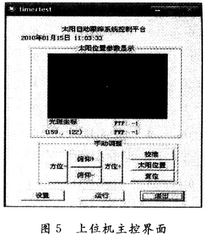
The control interface of the executable program of the host computer is shown in Figure 5. The control platform of the host computer has the functions of resetting, tracking and manual calibration of the sun position. The "Settings" button allows you to set the baud rate and adjust the time interval.
3 Experimental data analysis
The experiment was conducted in the Institute of Modern Optics of Suzhou University, and the data observation time was from late December to early January. Due to the large amount of data, Table 1 only lists some of the data recorded on January 7, 2010. The specific test methods are as follows:
(1) Parameter setting. Including setting the current time, baud rate, communication port, image sensor running time interval, etc.
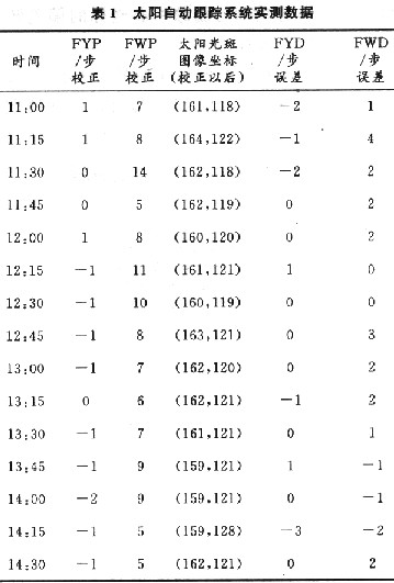
(2) Run the VC ++ program. The VC ++ program in the host computer first calls the sun function to return the solar altitude angle and azimuth angle at this time, and converts it into the number of steps required by the pitch and azimuth stepper motor. Only record the steps that need to be corrected in the txt file generated by Matlab.
(3) After the automatic calibration of the system is completed, Matlab writes a txt file again, and saves the image coordinates of the sun spot after the correction, and the deviation of the spot centroid coordinates and the image center coordinates. Record at this time.
(4) Repeat steps (2) and (3) every 5 minutes.
Figures 6 and 7 show the error curves of the solar altitude angle and azimuth angle. It can be seen from the curve that the absolute error of the solar automatic tracking controller based on the image sensor is relatively small and remains relatively stable. The analysis of the measured data shows that: in this system, the absolute error of altitude tracking is less than 0.12 °, and the absolute error of azimuth tracking is less than 0.08 °. After using the image sensor to track the sun, high accuracy and reliability are obtained. improve.


4 Conclusion
The tracking controller can continuously track the angle change of the sun and more accurately track the movement of the sun. When cloudy or cloudy, the system calls the clock algorithm to make the device continuously track. After experimental testing, all indicators have reached the design requirements.
The controller uses a low-speed processor to achieve the collection and positioning of the sun light spot, which can be applied to various solar energy equipment and improve the utilization rate of solar energy. If the stepping motor's micro-step control technology is used, that is, the subdivision technology is used to divide the stepper motor into a finer microstep, which can make the entire control system more precise and can be used to achieve a variety of Point light source detection.
The above is the Design of Automatic Solar Tracking Controller Using COMS Image Sensor we have listed for you. You can submit the following form to obtain more industry information we provide for you.
You can visit our website or contact us, and we will provide the latest consultation and solutions
Send Inquiry
Most Popular
lastest New
Send Inquiry
Privacy statement: Your privacy is very important to Us. Our company promises not to disclose your personal information to any external company with out your explicit permission.
Fill in more information so that we can get in touch with you faster
Privacy statement: Your privacy is very important to Us. Our company promises not to disclose your personal information to any external company with out your explicit permission.